Difference between revisions of "COPMM1"
From DIDEAS Wiki
m |
m (→History) |
||
| (22 intermediate revisions by 2 users not shown) | |||
| Line 1: | Line 1: | ||
| + | [[Medialab Documentation]] | ||
| + | |||
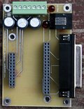
| + | [[image:Copmm1-rev0-top.jpg|right|thumb|120px|[[help:contents|top side]]]] | ||
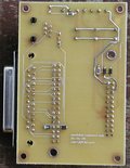
| + | [[image:Copmm1-rev0-bot.jpg|right|thumb|120px|[[help:contents|bottom side]]]] | ||
| + | |||
Breakout board for Accelnet Micro Module | Breakout board for Accelnet Micro Module | ||
*for Copley Controls Corp models : ACK-055-06, or ACK-090-04 | *for Copley Controls Corp models : ACK-055-06, or ACK-090-04 | ||
| Line 6: | Line 11: | ||
*bottom side text label "medialab/copmm1.pcb", "06/06/05" | *bottom side text label "medialab/copmm1.pcb", "06/06/05" | ||
*dimensions : 3.36 x 2.21" | *dimensions : 3.36 x 2.21" | ||
| + | |||
| + | |||
| + | ==Connectors== | ||
| + | * [[COPMM1-REV0_PINOUT#Power Header | 7 position terminal block]] with removable screw terminal plug (may be 4 position) | ||
| + | * [[COPMM1-REV0_PINOUT#DB25 | DB25 female]] | ||
| + | * [[COPMM1-REV0_PINOUT#RJ45 | RJ45 (8 pos)]] for RS-232 programming cable | ||
| + | * pair of female headers for mounting Copley motor amplifier | ||
| + | |||
| + | ==Indicators== | ||
| + | * "V.MOT" is a dual red/green with intensity related to average motor voltage | ||
| + | * "HV.PWR" indicates the presence of the HV motor supply | ||
| + | * "+5V" indicates the presence of 5V from Copley motor amp | ||
| + | |||
| + | ==Errors== | ||
| + | * Need to switch RxD and TxD on the RJ11 connector. Do this by cutting traces and adding jumper wires. | ||
| + | |||
== Designs == | == Designs == | ||
| Line 22: | Line 43: | ||
*[[Media:Accelnet_Micro_Module.pdf | Copley Amplifier Datasheet]] | *[[Media:Accelnet_Micro_Module.pdf | Copley Amplifier Datasheet]] | ||
| − | == | + | |
| + | ==Future Revisions== | ||
* change LED to gull-wing such as P504-ND | * change LED to gull-wing such as P504-ND | ||
| + | * remove "gnds" from power header - see page 9 of Accelnet for grounding method | ||
| − | + | *RS232 connector over board edge by ~0.1" | |
| − | * | + | *termblk header obscures 1/2 the lower line of text labels "CHS COM HV+...." |
| − | * | ||
| − | + | *DB25 plate mounting holes | |
| − | * | + | *smaller copley connector is 22 pins - not 24pins specified in SCH and PCB |
| + | |||
| + | *zener diode across caps for shunting brakeing current | ||
| + | *swap RS-232 signals on RJ11 | ||
| + | *add resistor across REF+- inputs | ||
| − | + | ==History== | |
| − | + | *06-08-05 : Submitted to AP-Circuits (received 2 copies) | |
| − | + | *06-10-05 : Ser #1,#2 built | |
| − | + | *06-10-05 : cut RxD, TxD traces on SER #1,#2 from RJ-11 ie swapped signals | |
| − | |||
| − | |||
| − | |||
| − | |||
| − | |||
| − | |||
| − | |||
| − | |||
| − | |||
| − | |||
| − | + | ==Bill of Materials== | |
| − | + | [[COPMM1_REV0_BOM | Bill of Materials]] | |
| − | |||
| − | |||
| − | |||
| − | |||
| − | |||
| − | |||
| − | |||
| − | |||
| − | |||
| − | |||
| − | |||
| − | |||
| − | |||
| − | |||
| − | |||
| − | |||
| − | |||
| − | |||
| − | |||
| − | |||
| − | | | ||
Latest revision as of 01:36, 11 June 2005
Breakout board for Accelnet Micro Module
- for Copley Controls Corp models : ACK-055-06, or ACK-090-04
Contents
Identification
- yellow tint PCB from AP-Circuits
- bottom side text label "medialab/copmm1.pcb", "06/06/05"
- dimensions : 3.36 x 2.21"
Connectors
- 7 position terminal block with removable screw terminal plug (may be 4 position)
- DB25 female
- RJ45 (8 pos) for RS-232 programming cable
- pair of female headers for mounting Copley motor amplifier
Indicators
- "V.MOT" is a dual red/green with intensity related to average motor voltage
- "HV.PWR" indicates the presence of the HV motor supply
- "+5V" indicates the presence of 5V from Copley motor amp
Errors
- Need to switch RxD and TxD on the RJ11 connector. Do this by cutting traces and adding jumper wires.
Designs
Reference
Future Revisions
- change LED to gull-wing such as P504-ND
- remove "gnds" from power header - see page 9 of Accelnet for grounding method
- RS232 connector over board edge by ~0.1"
- termblk header obscures 1/2 the lower line of text labels "CHS COM HV+...."
- DB25 plate mounting holes
- smaller copley connector is 22 pins - not 24pins specified in SCH and PCB
- zener diode across caps for shunting brakeing current
- swap RS-232 signals on RJ11
- add resistor across REF+- inputs
History
- 06-08-05 : Submitted to AP-Circuits (received 2 copies)
- 06-10-05 : Ser #1,#2 built
- 06-10-05 : cut RxD, TxD traces on SER #1,#2 from RJ-11 ie swapped signals

