POT4a
Contents
Revisions from POT4
- add 5pin, 1.25mm header for strain gauge
- removed unused input resistors and capacitors
- On POT4 a 1meg resistor was stacked on CC3 - this resistor added to SCH and PCB
- removed 4th order filter, changed 3way jumper to 2way
- 2nd order filter is now NON-Inverting
- input cable shield can be connected to COM via 0603 resistor
- changed PCB pattern for output driver caps to CAP200-SQ (accurately represents component shape)
- changed 0805 output cable CAP to 1206. Panasonic X5R series @ 25V 1uf to 10uF!
- added 10 turn POT for variable gain (optional)
- changed CD2 (0.1u in derivative circuit) to 1206 size (was 0805)
POT4a Power Supply
POT4a Header Pinouts
Voltage Reference
Discussion of the voltage reference.
Identification
- POT4a is a green PCB with white silk screen on two sides.
- Dimensions 1.75" x 0.85"
- Two mounting holes (diameter = 0.125"), top side clearance > 0.25"
- The color of DL1,DL2 indicates the input configuration of the board
Led Indicators
- (DL1, DL2) : A pair of single LEDs indicate the present of power. These LEDs are aligned with the power input to the boards.
- DK1 : The intensity of this dual RED/GREEN LED indicates the voltage of the "position signal".
Assembly Notes
- SN1 : Vref=9.79V, CB1,CB3=2.2uF, CD1=1uF has LP2 and dX/dt; not populated adjustable gain; additional CB caps could be populated
Frequency Response
Position Signal
The position signal is filtered as followed:
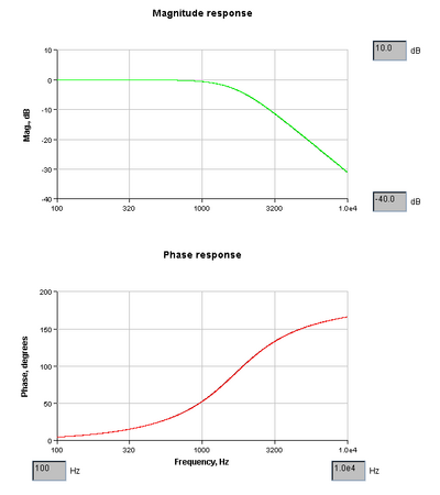
- 1st order input filter : 5.8KHz typical
- selectable 2nd order LP : 1.68 KHz, Q=0.7; Stallen-Key LP
- 1st order differential output filter : 723 Hz
Velocity Signal
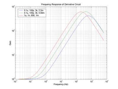
The velocity signal is the derivative of the position signal after it traverse the input filter and optional 2nd order LP filter. The BW limited derivative is valid from around 0.2Hz to 125Hz.
Using the values of recommenced component values of : 0.1u, 100pF, 3K, 4.99M,
Vout = k * dVin/dT where k = 1/2080 (+-10%) in units of per sec.
The constant k is the average of 5 data points from 13 to 265 Hz.
The output of the derivative is filtered by a 1st order differential output filter at 723 Hz.
Graphs
The following indicates the frequency response of the 2nd order LP filter and on the right the response of the derivative operation. These are graphs DO NOT represent the overall system response. Additional phase shift results from the input and output filters.
| 2nd order LP | Derivative Response |
|---|---|
 |
Design Files
- Media:Pot4a-sch-reva-062205.pdf
- Media:Rpot4a-pcb-top-reva-061605.pdf
- Media:Rpot4a-pcb-bot-reva-061605.pdf
- Gerber files and Tango DOS source (6-16-05)
Bill of Materials
Assembly
- RL1,2 = 2.74k
- RR1,4 = 499ohm 1206


